Dr. Robert P. Hesketh
Email: Hesketh@Rowan.edu
Experimental Research Program
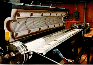
An adiabatic, tubular flow reactor facility is constructed to obtain data for the oxidation of organic compounds in the temperature range of 800 - 1100°C. This temperature region is typical of the post-flame region of rotary kilns and fluidized beds. The facility is designed to operate under both, the laminar and near-transition turbulent regimes. The flow reactor is operated with nitrogen as an inert carrier gas, and either air or pure oxygen serve as an oxidizer. The facility has been designed to handle the maximum nitrogen flow rate of 10 g/s. Brooks model 5800 series mass flow controllers with the four-channel control unit have been installed to maintain constant mass flow rates of carrier, oxidizer and reactant gas components. Stainless steel serves as the material of construction for the process piping and fittings due to its chemical inertness. The gas preheater, mixing section and the exhaust section are constructed of a high-temperature SS-310 material. The main reactor and the water-cooled, gas sampling probe are made of quartz tubes because of its thermal and chemical inertness at high combustion temperatures.
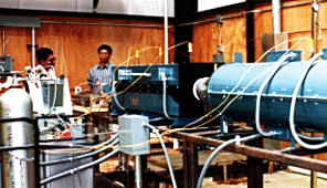
In principle, the flow reactor system consists of the following major sections:
(a) Gas preheating: The oxidizer is mixed with nitrogen before the gas preheater. A packed bed of inert monolith structures in a single-zone electric furnace (rated at 1200°C maximum temperature) serves as the gas preheater. The monolith packing provides large surface area for gas heat transfer, and increases the gas residence time at low pressure drop. A 1.5 m long, 0.13 m ID heated zone is sufficient to preheat 10 g/s of gas from ambient temperatures up to 1100 oC. The outlet gas temperature is monitored by controlling the furnace power. The heated gas mixture then enters the mixing section, where the reactant species is added under turbulent conditions. The location at which this reactant is introduced is recognized as the starting point for the combustion reaction
(b) Mixing nozzle: The reactant-oxidizer mixing section is the most critical part of the flow reactor system, since an instantaneous gas mixing is desired compared to the total reaction time. The convergent-divergent venturi section is made of moldable Silica powder and aids in a proper mixing of oxidizer with reactant. The gas mixing nozzle is placed in the venturi throat and the reactant is introduced as turbulent jets in the radially outward direction. The mixing nozzle extends into the venturi by 0.1 m in order to eliminate any entrance effects at the throat entry. The carrier-oxidizer gas mixture flows through eight, 5 mm diameter peripheral holes into the throat, whereas the reactant is forced out through eight, 1 mm diameter orifices of the nozzle. The turbulence created because of the jetting effect cause intense mixing in the venturi section. The gas mixture is then stabilized by passing through a gradually diverging (at 5 deg. angle) diffuser section. The diffuser section is used to minimize flow separation of the reaction mixture flowing into the quartz test section.
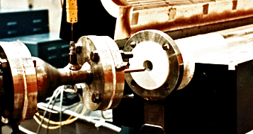
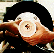
(c) Reaction zone: The chemical reaction initiates after the mixing nozzle and is continued downstream. In order to study the effect of reactor diameter on reaction kinetics, slide-in cylinders of smaller diameters are designed to fit inside the main reactor tube. The reactor body consists of a 0.1 m ID., thick-walled quartz tube with two quartz slide-ins of 0.03 m and 0.5 m ID. The main reactor is approximately 2.0 m in length and the reaction zone is between 1.3 to 1.8 m long depending on the reactor diameter under consideration. The reactor assembly is enclosed in a horizontal split-tube, three-zone temperature controlled furnace. The furnace is designed for a 20 kW total power and is rated at maximum operating temperature of 1200°C. The three-zone temperature controllers permit independent control of power input to individual sections of the furnace, thus, attaining a flat temperature profile across most of the reactor length.
(d) Gas exhaust: The hot exhaust gas mixture is quenched by water-spray and air-dilution techniques. In the quenching chamber, a fine cone-shaped water spray is obtained via three wall-mounted spray nozzles. In addition, a provision is made to dilute the exhaust gas with compressed air. The cooled, exhaust gas is then vented to the atmosphere through a tall, well-insulated gas stack. Precautionary measures have been taken by making a proper use of high temperature stack materials.
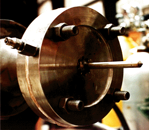
(e) Gas sampling: The reaction progress is monitored by extracting gas samples at various axial locations using a water-cooled quartz probe. The temperature at the sample location is measured by a type K thermocouple attached to the probe. The sampling probe diameter is designed to be as small as possible in order to minimize flow disturbance and turbulence at the sampling point. The quartz probe is enclosed in a SS 310 sleeve to protect it from any structural damage. The probe sleeve extends through the reactor downstream and is installed on a traverse mechanism. A screw-driven probe drive unit gives a precise movement to the probe sliding in the reactor. The gas samples from 15 axial locations are withdrawn and quenched inside the water-cooled probe to extinguish any chemical reactions occurring after the sample point. These gas samples are stored under temperature controlled conditions in a 16- loop Valco sampling valve assembly. The valve assembly consists of an electric oven with a set-point temperature controller along with 16 sampling loops for an intermediate sample storage.

(f) Gas analysis: The multi-loop sampling valve is controlled by an electric actuator for loading and/or unloading of the gas samples. The need for an intermediate storage facility arises because of prolonged sample analysis in detection system compared to a much shorter time for the sample collection. The gas samples are analyzed successively on a Gas Chromatograph/Mass Spectrometer Detector (GC/MSD), an industrial grade NO/NOx chemiluminiscence and CO2 NDIR detectors. Analysis of permanent gases such as H2, O2, N2 and CO are performed under cryogenic conditions.
Experimental Conditions
The following operating conditions are based on the flow, pressure drop,
heat transfer calculations and economic analysis:

	Carrier gas design flow rate	=  10 g/sec
	Operating temperature		=  800 - 1100°C
	Equivalence ratio		=  0.1 - 10
	Operating pressure		=  atmospheric

	Mass flow controller range:
		Nitrogen		=  0 - 600 SLM
		Oxygen			=  0 - 100 SLM
		Reactant		=  0 - 50 SLM

	Experimental test section:
		Reactor ID.		=  3.0, 5.0 and 10.0 cm
		Reactor length		=  130 - 180 cm
		Reaction time		=  0.11 - 2.5 sec
		Mixing time		=  0.01 sec

	Reynolds number (NRe) for
		Gas mixing section	=  600 - 20,000
		test section		=  300 - 9,000
This research is being funded by the National Science Foundation Grant No. CTS-9211905 and a DuPont Young Professor Grant.
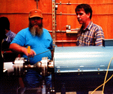
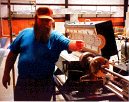
This reactor was designed and constructed by Miland V. Kantak under the supervision of Dr. Hesketh. Fabrication of the reactor and related parts was done by Terry Hutson, Don Harris, David Jones and Mike Teal under the supervision of Ted Hope.
Return to the Dr. Robert P. Hesketh


