Wavlet Tutorial - Part 2
by Robi Polikar
Fundamentals: the fourier Transform and The Short Term Fourier Transform
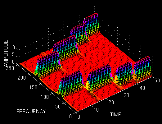
Fundamentals
Let's have a short review of the first part. We basically need Wavelet Transform (WT) to analyze non-stationary signals, i.e., whose frequency response varies in time. I have written that Fourier Transform (FT) is not suitable for non-stationary signals, and I have shown examples of it to make it more clear. For a quick recall, let me give the following example. Suppose we have two different signals. Also suppose that they both have the same spectral components, with one major difference. Say one of the signals have four frequency components at all times, and the other have the same four frequency components at different times. The FT of both of the signals would be the same, as shown in the example in part 1 of this tutorial. Although the two signals are completely different, their (magnitude of) FT are the SAME !. This, obviously tells us that we can not use the FT for non-stationary signals.
But why does this happen? In other words, how come both of the signals have the same FT? HOW DOES FOURIER TRANSFORM WORK ANYWAY?
An Important Milestone in Signal Processing:
The Fourier Transform
I will not go into the details of FT for two reasons:
- It is too wide of a subject to discuss in this tutorial.
- It is not our main concern anyway.
However, I would like to mention a couple important points again for two reasons:
- It is a necessary background to understand how WT works.
- It has been by far the most important signal processing tool for many (and I mean many many) years.
In 19th century (1822*, to be exact, but you do not need to know the exact time. Just trust me that it is far before than you can remember), the French mathematician J. Fourier, showed that any periodic function can be expressed as an infinite sum of periodic complex exponential functions. Many years after he had discovered this remarkable property of (periodic) functions, his ideas were generalized to first non-periodic functions, and then periodic or non-periodic discrete time signals. It is after this generalization that it became a very suitable tool for computer calculations. In 1965, a new algorithm called fast Fourier Transform (FFT) was developed and FT became even more popular.
(* I thank Dr. Pedregal for the valuable information he has provided)
Now let us take a look at how Fourier transform works:
FT decomposes a signal to complex exponential functions of different frequencies. The way it does this, is defined by the following two equations:
$X(f) = \int_{-\infty}^{\infty} x(t) \cdot e^{-2 j \pi f t} dt$
$x(t) = \int_{-\infty}^{\infty} X(f) \cdot e^{2 j \pi f t} df$
Figure 2.1
$x(t) = \int_{-\infty}^{\infty} X(f) \cdot e^{2 j \pi f t} df$
Figure 2.1
In the above equation, t stands for time, f stands for frequency, and x denotes the signal at hand. Note that x denotes the signal in time domain and the X denotes the signal in frequency domain. This convention is used to distinguish the two representations of the signal. Equation (1) is called the Fourier transform of x(t), and equation (2) is called the inverse Fourier transform of X(f), which is x(t).
For those of you who have been using the Fourier transform are already familiar with this. Unfortunately many people use these equations without knowing the underlying principle.
Please take a closer look at equation (1):
The signal x(t), is multiplied with an exponential term, at some certain frequency "f", and then integrated over ALL TIMES !!! (The key words here are "all times" , as will explained below).
Note that the exponential term in Eqn. (1) can also be written as:
$cos(2 \pi f t) \cdot sin(2 \pi f t)$
The above expression has a real part of cosine of frequency f, and an imaginary part of sine of frequency f. So what we are actually doing is, multiplying the original signal with a complex expression which has sines and cosines of frequency f. Then we integrate this product. In other words, we add all the points in this product. If the result of this integration (which is nothing but some sort of infinite summation) is a large value, then we say that : the signal x(t), has a dominant spectral component at frequency "f". This means that, a major portion of this signal is composed of frequency f. If the integration result is a small value, than this means that the signal does not have a major frequency component of f in it. If this integration result is zero, then the signal does not contain the frequency "f" at all.
It is of particular interest here to see how this integration works: The signal is multiplied with the sinusoidal term of frequency "f". If the signal has a high amplitude component of frequency "f", then that component and the sinusoidal term will coincide, and the product of them will give a (relatively) large value. This shows that, the signal "x", has a major frequency component of "f".
However, if the signal does not have a frequency component of "f", the product will yield zero, which shows that, the signal does not have a frequency component of "f". If the frequency "f", is not a major component of the signal "x(t)", then the product will give a (relatively) small value. This shows that, the frequency component "f" in the signal "x", has a small amplitude, in other words, it is not a major component of "x".
Now, note that the integration in the transformation equation (Eqn. 1) is over time. The left hand side of (1), however, is a function of frequency. Therefore, the integral in (1), is calculated for every value of f.
IMPORTANT(!) The information provided by the integral, corresponds to all time instances, since the integration is from minus infinity to plus infinity over time. It follows that no matter where in time the component with frequency "f" appears, it will affect the result of the integration equally as well. In other words, whether the frequency component "f" appears at time t1 or t2 , it will have the same effect on the integration. This is why Fourier transform is not suitable if the signal has time varying frequency, i.e., the signal is non-stationary. If only the signal has the frequency component "f" at all times (for all "t" values), then the result obtained by the Fourier transform makes sense.
Note that the Fourier transform tells whether a certain frequency component exists or not. This information is independent of where in time this component appears. It is therefore very important to know whether a signal is stationary or not, prior to processing it with the FT.
The example given in part one should now be clear. I would like to give it here again:
Look at the following figure, which shows the signal:
$x(t) = cos(2 \pi \cdot 5 t) + cos(2 \pi \cdot 10 t) + cos(2 \pi \cdot 20 t) + cos(2 \pi \cdot 50 t)$
that is , it has four frequency components of 5, 10, 20, and 50 Hz., all occurring at all times.
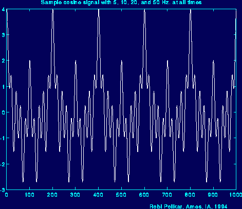
Figure 2.2
And here is the FT of it. The frequency axis has been cut here, but theoretically it extends to infinity (for continuous Fourier transform (CFT). Actually, here we calculate the discrete Fourier transform (DFT), in which case the frequency axis goes up to (at least) twice the sampling frequency of the signal, and the transformed signal is symmetrical. However, this is not that important at this time.)
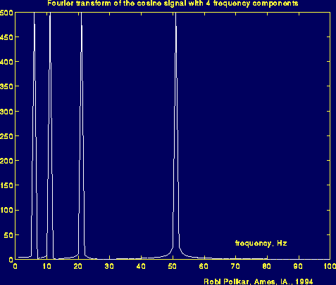
Figure 2.3
Note the four peaks in the above figure, which correspond to four different frequencies.
Now, look at the following figure: Here the signal is again the cosine signal, and it has the same four frequencies. However, these components occur at different times.
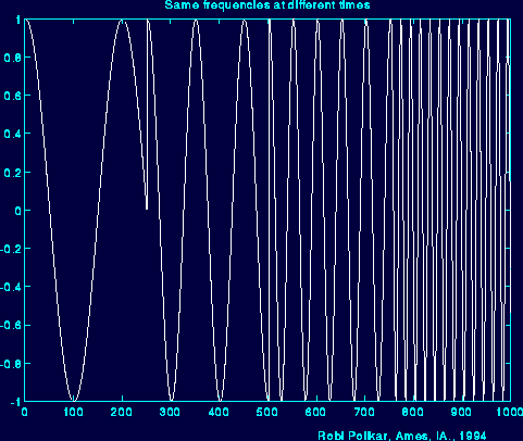
Figure 2.4
And here is the Fourier transform of this signal:
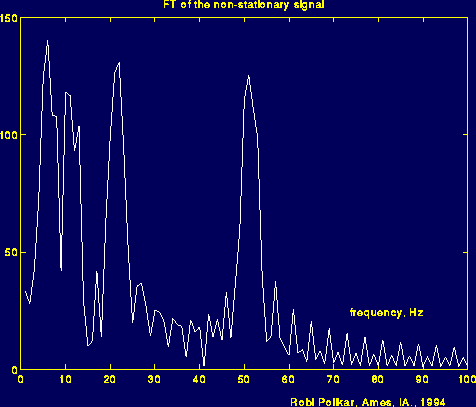
Figure 2.5
What you are supposed to see in the above figure, is it is (almost) same with the previous FT figure. Please look carefully and note the major four peaks corresponding to 5, 10, 20, and 50 Hz. I could have made this figure look very similar to the previous one, but I did not do that on purpose. The reason of the noise like thing in between peaks show that, those frequencies also exist in the signal. But the reason they have a small amplitude , is because, they are not major spectral components of the given signal, and the reason we see those, is because of the sudden change between the frequencies. Especially note how time domain signal changes at around time 250 (ms) (With some suitable filtering techniques, the noise like part of the frequency domain signal can be cleaned, but this has not nothing to do with our subject now. If you need further information please send me an e-mail).
By this time you should have understood the basic concepts of Fourier transform, when we can use it and we can not. As you can see from the above example, FT cannot distinguish the two signals very well. To FT, both signals are the same, because they constitute of the same frequency components. Therefore, FT is not a suitable tool for analyzing non-stationary signals, i.e., signals with time varying spectra.
Please keep this very important property in mind. Unfortunately, many people using the FT do not think of this. They assume that the signal they have is stationary where it is not in many practical cases. Of course if you are not interested in at what times these frequency components occur, but only interested in what frequency components exist, then FT can be a suitable tool to use.
So, now that we know that we can not use (well, we can, but we shouldn't) FT for non-stationary signals, what are we going to do?
Remember that, I have mentioned that wavelet transform is only (about) a decade old. You may wonder if researchers noticed this non-stationarity business only ten years ago or not.
Obviously not.
Apparently they must have done something about it before they figured out the wavelet transform....?
Well..., they sure did...
They have come up with ...
LINEAR TIME FREQUENCY REPRESENTATIONS
The Short Term Fourier Transform
So, how are we going to insert this time business into our frequency plots? Let's look at the problem in hand little more closer.
What was wrong with FT? It did not work for non-stationary signals. Let's think this: Can we assume that , some portion of a non-stationary signal is stationary?
The answer is yes.
Just look at the third figure above. The signal is stationary every 250 time unit intervals.
You may ask the following question?
What if the part that we can consider to be stationary is very small?
Well, if it is too small, it is too small. There is nothing we can do about that, and actually, there is nothing wrong with that either. We have to play this game with the physicists' rules.
If this region where the signal can be assumed to be stationary is too small, then we look at that signal from narrow windows, narrow enough that the portion of the signal seen from these windows are indeed stationary.
This approach of researchers ended up with a revised version of the Fourier transform, so-called : The Short Time Fourier Transform (STFT)
There is only a minor difference between STFT and FT. In STFT, the signal is divided into small enough segments, where these segments (portions) of the signal can be assumed to be stationary. For this purpose, a window function "w" is chosen. The width of this window must be equal to the segment of the signal where its stationarity is valid.
This window function is first located to the very beginning of the signal. That is, the window function is located at t=0. Let's suppose that the width of the window is "T" s. At this time instant (t=0), the window function will overlap with the first T/2 seconds (I will assume that all time units are in seconds). The window function and the signal are then multiplied. By doing this, only the first T/2 seconds of the signal is being chosen, with the appropriate weighting of the window (if the window is a rectangle, with amplitude "1", then the product will be equal to the signal). Then this product is assumed to be just another signal, whose FT is to be taken. In other words, FT of this product is taken, just as taking the FT of any signal.
The result of this transformation is the FT of the first T/2 seconds of the signal. If this portion of the signal is stationary, as it is assumed, then there will be no problem and the obtained result will be a true frequency representation of the first T/2 seconds of the signal.
The next step, would be shifting this window (for some t1 seconds) to a new location, multiplying with the signal, and taking the FT of the product. This procedure is followed, until the end of the signal is reached by shifting the window with "t1" seconds intervals.
The following definition of the STFT summarizes all the above explanations in one line:
$STFT_X^{(\omega)}(t,f) = \int_t \left[ x(t) \cdot \omega^*(t - t') \right] \cdot e^{-j 2 \pi f t} dt$
Figure 2.6
Figure 2.6
Please look at the above equation carefully. x(t) is the signal itself, w(t) is the window function, and * is the complex conjugate. As you can see from the equation, the STFT of the signal is nothing but the FT of the signal multiplied by a window function.
For every t' and f a new STFT coefficient is computed (Correction: The "t" in the parenthesis of STFT should be "t'". I will correct this soon. I have just noticed that I have mistyped it).
The following figure may help you to understand this a little better:
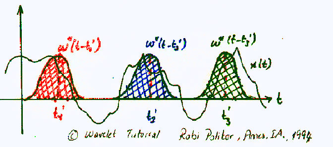
Figure 2.7
The Gaussian-like functions in color are the windowing functions. The red one shows the window located at t = t1', the blue shows t = t2', and the green one shows the window located at t = t3'. These will correspond to three different FTs at three different times. Therefore, we will obtain a true time-frequency representation (TFR) of the signal.
Probably the best way of understanding this would be looking at an example. First of all, since our transform is a function of both time and frequency (unlike FT, which is a function of frequency only), the transform would be two dimensional (three, if you count the amplitude too). Let's take a non-stationary signal, such as the following one:
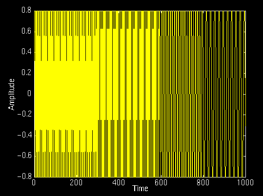
Figure 2.8
In this signal, there are four frequency components at different times. The interval 0 to 250 ms is a simple sinusoid of 300 Hz, and the other 250 ms intervals are sinusoids of 200 Hz, 100 Hz, and 50 Hz, respectively. Apparently, this is a non-stationary signal. Now, let's look at its STFT:
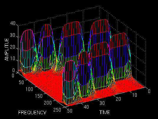
Figure 2.9
As expected, this is two dimensional plot (3 dimensional, if you count the amplitude too). The "x" and "y" axes are time and frequency, respectively. Please, ignore the numbers on the axes, since they are normalized in some respect, which is not of any interest to us at this time. Just examine the shape of the time-frequency representation.
First of all, note that the graph is symmetric with respect to midline of the frequency axis. Remember that, although it was not shown, FT of a real signal is always symmetric, since STFT is nothing but a windowed version of the FT, it should come as no surprise that STFT is also symmetric in frequency. The symmetric part is said to be associated with negative frequencies, an odd concept which is difficult to comprehend, fortunately, it is not important; it suffices to know that STFT and FT are symmetric.
What is important, are the four peaks; note that there are four peaks corresponding to four different frequency components. Also note that, unlike FT, these four peaks are located at different time intervals along the time axis. Remember that the original signal had four spectral components located at different times.
Now we have a true time-frequency representation of the signal. We not only know what frequency components are present in the signal, but we also know where they are located in time.
It is grrrreeeaaatttttt!!!! Right?
Well, not really!
You may wonder, since STFT gives the TFR of the signal, why do we need the wavelet transform. The implicit problem of the STFT is not obvious in the above example. Of course, an example that would work nicely was chosen on purpose to demonstrate the concept.
The problem with STFT is the fact whose roots go back to what is known as the Heisenberg Uncertainty Principle. This principle originally applied to the momentum and location of moving particles, can be applied to time-frequency information of a signal. Simply, this principle states that one cannot know the exact time-frequency representation of a signal, i.e., one cannot know what spectral components exist at what instances of times. What one can know are the time intervals in which certain band of frequencies exist, which is a resolution problem.
The problem with the STFT has something to do with the width of the window function that is used. To be technically correct, this width of the window function is known as the support of the window. If the window function is narrow, than it is known as compactly supported. This terminology is more often used in the wavelet world, as we will see later.
Here is what happens:
Recall that in the FT there is no resolution problem in the frequency domain, i.e., we know exactly what frequencies exist; similarly we there is no time resolution problem in the time domain, since we know the value of the signal at every instant of time. Conversely, the time resolution in the FT, and the frequency resolution in the time domain are zero, since we have no information about them. What gives the perfect frequency resolution in the FT is the fact that the window used in the FT is its kernel, the $e^{j \omega t}$ function, which lasts at all times from minus infinity to plus infinity. Now, in STFT, our window is of finite length, thus it covers only a portion of the signal, which causes the frequency resolution to get poorer. What I mean by getting poorer is that, we no longer know the exact frequency components that exist in the signal, but we only know a band of frequencies that exist:
In FT, the kernel function, allows us to obtain perfect frequency resolution, because the kernel itself is a window of infinite length. In STFT is window is of finite length, and we no longer have perfect frequency resolution. You may ask, why don't we make the length of the window in the STFT infinite, just like as it is in the FT, to get perfect frequency resolution? Well, than you loose all the time information, you basically end up with the FT instead of STFT. To make a long story real short, we are faced with the following dilemma:
If we use a window of infinite length, we get the FT, which gives perfect frequency resolution, but no time information. Furthermore, in order to obtain the stationarity, we have to have a short enough window, in which the signal is stationary. The narrower we make the window, the better the time resolution, and better the assumption of stationarity, but poorer the frequency resolution:
Narrow window ===>good time resolution, poor frequency resolution.
Wide window ===>good frequency resolution, poor time resolution.
In order to see these effects, let's look at a couple examples: I will show four windows of different length, and we will use these to compute the STFT, and see what happens:
The window function we use is simply a Gaussian function in the form:
$e^{-a \left( \frac{t^2}{2} \right)}$
where a determines the length of the window, and t is the time. The following figure shows four window functions of varying regions of support, determined by the value of a. Please disregard the numeric values of a since the time interval where this function is computed also determines the function. Just note the length of each window. The above example given was computed with the second value, a = 0.001. I will now show the STFT of the same signal given above computed with the other windows.
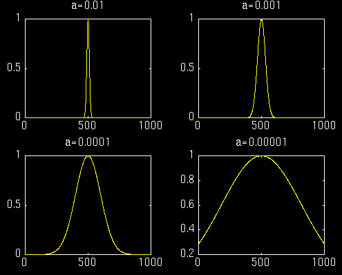
Figure 2.10
First let's look at the first most narrow window. We expect the STFT to have a very good time resolution, but relatively poor frequency resolution:
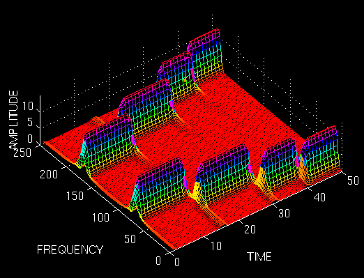
Figure 2.11
The above figure shows this STFT. The figure is shown from a top bird-eye view with an angle for better interpretation. Note that the four peaks are well separated from each other in time. Also note that, in frequency domain, every peak covers a range of frequencies, instead of a single frequency value. Now let's make the window wider, and look at the third window (the second one was already shown in the first example).
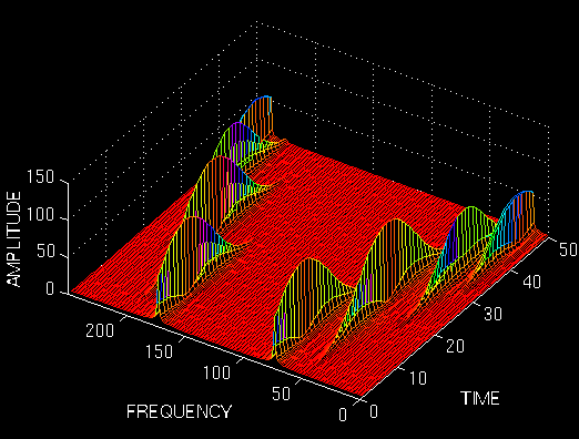
Figure 2.12
Note that the peaks are not well separated from each other in time, unlike the previous case, however, in frequency domain the resolution is much better. Now let's further increase the width of the window, and see what happens:
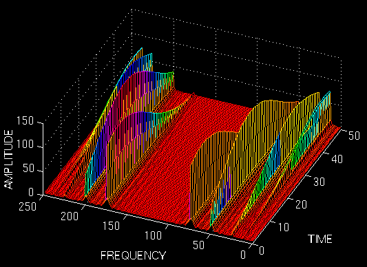
Figure 2.13
Well, this should be of no surprise to anyone now, since we would expect a terrible (and I mean absolutely terrible) time resolution.
These examples should have illustrated the implicit problem of resolution of the STFT. Anyone who would like to use STFT is faced with this problem of resolution. What kind of a window to use? Narrow windows give good time resolution, but poor frequency resolution. Wide windows give good frequency resolution, but poor time resolution; furthermore, wide windows may violate the condition of stationarity. The problem, of course, is a result of choosing a window function, once and for all, and use that window in the entire analysis. The answer, of course, is application dependent: If the frequency components are well separated from each other in the original signal, than we may sacrifice some frequency resolution and go for good time resolution, since the spectral components are already well separated from each other. However, if this is not the case, then a good window function, could be more difficult than finding a good stock to invest in.
By now, you should have realized how wavelet transform comes into play. The Wavelet transform (WT) solves the dilemma of resolution to a certain extent, as we will see in the next part.
This completes Part II of this tutorial. The continuous wavelet transform is the subject of the Part III of this tutorial. If you did not have much trouble in coming this far, and what have been written above make sense to you, you are now ready to take the ultimate challenge in understanding the basic concepts of the wavelet theory.
Send your comments / questions to: polikar@rowan.edu
All Rights Reserved. This tutorial is intended for educational purposes only. Unauthorized copying, duplicating and publishing is strictly prohibited.
Robi Polikar
Rowan University
Phone: (856) 256 5372
polikar@rowan.edu