Assignment #1. Complete in groups of 3. Due Feb. 1. Check out the homework policy. Don't forget Bernoulli's!
Assignment #3. Complete in groups of 3. Due Feb. 17.
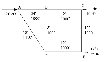
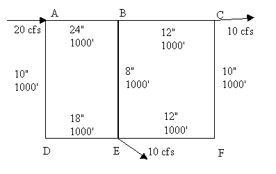
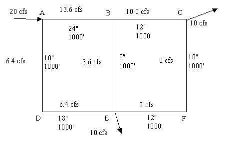
1. Estimating Pressure in a pipe network. Refer to the figure
shown below. Pressure at D is 70 psi. Assume that all
of the points are at 0 ft elev., except F which is at 5 ft. What is the
pressure at A, B and F? Neglect the effect of velocity head.
Use f = 0.012 for all pipes. Assume specific weight is 62.4 lb/ft^3.
Note: do not neglect the effect of the elevation change when determining
the pressure at F.
2. Elevated Storage Problem - Low Demand. Given the following, estimate
the flow from the pump to the city and from the city to the elevated storage.
Using Bernoulli's, also estimate the pressure at the city (neglect velocity
head).
zp= 5 ft Ep= 205
ft zc= 25 ft
QD = 4000 gal/min ze=
200 ft CH = 100
Dpc= 36 in Lpc=
25000 ft Dce= 24 in
Lce= 4000 ft
3. Elevated Storage Problem - High demand. Given the same data as in problem 2, except QD = 12,000 gallons/min, estimate the flow from the pump to the city and the elevated storage to the city. Using Bernoulli's, also estimate the pressure at the city (neglect velocity head).
Assignment #4. Complete in groups of 3. Due Feb. 22.
Complete the Theissen network homework problem handed out in class.
Assignment #5. Complete in groups of 3. Due March 10.
1. Estimate peak flow using the rational method. The drainage area is 10 acres. Assume that the intensity of a 5 minute design rainfall is 1.4 in/hr, the intensity of a 10 minute design rainfall is 1.25 in/hr and the intensity of a 20 minute design rainfall is 1 in/hr. Use the Table provided in class to estimate runoff coefficients (use the average of the high and low value given in the Table).
(a) The time of concentration for the area is 5 minutes. The area is asphalt pavement.2. Estimate groundwater movement using Darcy's Law. Two wells, located along a streamline are 1000 m apart. The difference in head between the two wells is 0.5 m. Use Table 4.1 to estimate K and n.
(b) Same as (a) but the area is a lawn with sandy soil and flat slope.
(c) Same as (a) but the time of concentration is 20 minutes.
(a) Estimate the specific discharge if the sediment is clay3. A well is pumped at steady-state and the cone of depression observed at two points. You are given the following information: radius of well = 12". Thickness of aquifer = 108 ft. Drawdown (distance from original water table to existing water table) is 11.1 ft and 7.0 ft at 57 ft and 127 ft from the pumping well. Pump rate is 310 gpm.
(b) Estimate the average velocity if the sediment is sand
(c) Estimate the flow rate through a square meter of soil if the sediment is gravel and sand
(a) State your assumptions (that allow you to use the Thiem equation to solve this problem)4. A well is pumped for a short period of time at 1250 L/Min. Drawdown is observed in an observation well 40 m away. Given the following data, use the Theis Method to estimate transmissivity and the storage coefficient.
(b) Estimate the hydraulic conductivity of the sediment around the well
(c) Estimate the drawdown in the well.
| Time, hr |
|
|
|
|
|
|
|
|
|
|
|
|
|
|
|
|
Assignment #6. Complete in groups of 3. Due March 24.
1. Develop a recurrence interval vs. peak flow curve for Buffalo Creek,
near Freeport, PA.
(a) Retrieve Data: Go to the United States Geological Survey site at http://h2o.er.usgs.gov/. Under "WATER DATA" select "Historical (NWIS-W)". Select Pennsylvania on the map. Enter station # 03049000 and click on the "retrieve data" button. This should get you to the data site for Buffalo Creek, near Freeport, PA (Butler County). Select "Peak Flow". Select "Only Annual Peaks", "Tab Delimited Text Data File", and "MM/DD/YYYY" and click on the "retrieve data" button. You should be at the peak flow raw data site for station # 03049000. The top of the file has some general information for the site. About 30 lines down, the actual data starts. The easiest way to get the data into Excel is to cut and paste the data (just the numbers) into Excel, select the data (it will be in one column of cells), then select "Text to Columns" under the Excel "Data" menu. This allows you to split the text lines into separate columns. Just follow the wizard. Once you've separated the data columns, delete all of the columns except the 3rd and 4rth (the date and peak flow).2. Size a drinking water reservoir on the Little River, near Norman, OK. The reservoir is to supply 6 mdg to the City of Norman.
(b) Report the following descriptive data for the station: Latitude and longitude, Basin name, State, County, Stream name, Station #, Drainage basin area, and Gage datum (note: NGVD stands for National Geodetic Vertical Datum).
(c) Calculate the recurrence interval for each peak flow, using the plotting position and Gumbel distributions.
(d) Make a plot of Peak flow (y-axis) vs b (x-axis). To plot the plotting position results, you'll need to convert recurrence intervals to b using equation 5.4. At the top of the graph, show the corresponding recurrence intervals (use equation 5.4 again).
(e) Using your plot, answer the following questions for both distributions (plotting position and Gumbel):
- What recurrence interval is associated with a peak flow of 12,000 cfs? I suggest reading b's off your plot, then converting them to recurrence intervals using equation 5.4.
- What is the probability of a flood equal to or greater than 12,000 cfs occurring at least once in a 50 yr period? Use equation 5.3.
- If you were going to design a hydraulic structure on this stream near station # 03049000, what flow would you design for if the flood recurrence interval was supposed to be 25 yrs? What about 100 yrs?
(a) Retrieve Data: Go to the United States Geological Survey site at http://h2o.er.usgs.gov/. Under "WATER DATA" select "Historical (NWIS-W)". Select Oklahoma on the map. Select "list of Counties in Oklahoma". Select "Cleveland, OK". Select "Little River near Norman Oklahoma". Select "Historical Stream flow Daily Values". Note that the data record only goes from 10/1/51 to 9/30/55. Select "Tab Delimited Text Data File", and "MM/DD/YYYY" and click on the "retrieve data" button. You should be at the daily mean stream flow data site for station # 07229500. The top of the file has some general information for the site. About 30-40 lines down, the actual data starts. The easiest way to get the data into Excel is to cut and paste the data (just the numbers) into Excel, select the data (it will be in one column of cells), then select "Text to Columns" under the Excel "Data" menu. Choose the "fixed width" option and hit "Finish". All you'll have is two columns: the date and mean daily stream flow in cfs.
(b) Report the following descriptive data for the station: Latitude and longitude, Basin name, State, County, Stream name, Station #, Drainage basin area, and Gage datum (note: NGVD stands for National Geodetic Vertical Datum).
(c) Convert the date information to number. The first day (10/1/51) will be day 1, the second day will be day 2, etc. First, copy the date information into another column, then change the cell format to number (with 0 decimal places). This converts the date format into a number (a big number). Second, make the resulting number series start at 1 by simply subtracting the appropriate value from all of the day numbers. Convert the daily mean discharge (cfs) into cumulative million cubic feet. Plot the resulting information using Excel. The y axis should be Cumulative Discharge (Million Cubic Feet) and the x axis should be day. The major unit on the y axis should be 200 million cubic feet; on the x axis it should be 365 days. Make your data points as small as possible. Do this by clicking on the data point in the legend. This takes you to the "Format Legend Key" menu. Make the size of the Marker 2 pts. Print the graph. Don't give me the raw data.
(d) Determine the water supply demand in million cubic feet per four years and plot it as a demand line on the graph in light pencil, in a convenient location (out of the way of your data points). Draw lines (parallel to the water supply demand line) from the appropriate points on the Little River cumulative flow data (points where high flow become low flow for extended periods. Identify the greatest water deficit. This is the required volume of the reservoir.
(e) We've ignored at least three potentially important factors in solving this problem. One is a source of water loss from the planned reservoir, especially in the hot Oklahoma summer (hint). Another factor is potential sources of extra water (see the "Map of region surrounding station" available on the station's USGS site). The map shows a drinking water reservoir that was built on the Little River in the 50/60's (which inundated the station). The Little river is the major source of water for the reservoir; however, it is just one of the blue lines extending away from the reservoir (hint). The third factor is potential groundwater-surface water interactions. Name the first two factors.
Assignment #7. Complete in groups of 3. Due April
1. Complete these problems by hand (except problem 5). If you wish,
check them using FlowMaster. Froude Number = V / (g y)0.5 (If
you compare to the Froude number calculated by FlowMaster, note that it
assumes g = 32.174 ft/s2)
1. A 3 ft wide natural stream (clean) has n = 0.03, slope = 0.09 and flow depth = 1 ft. Assume the stream is rectangular in cross-section. (a) Estimate the discharge in cfs. Use the Froude number to determine if the flow is super or sub-critical. (b) If the stream described in part A has a discharge of 20 cfs, find the depth of flow (i.e., normal depth for a given flow). Use the Froude number to determine if the flow is super or sub-critical.
2. A very long 2 ft diameter corrugated metal storm drain (n = 0.024) diverts water under a parking lot. The slope is 0.009. (a) What is the full flow discharge? Use Figure 10.3 to determine (b) the discharge that will occur when the depth of flow is 1.7 ft, and (c) the maximum possible discharge. (d) Use Figure 10.3 and the Froude number to determine if the flow is super or sub-critical when the flow depth is 1.7 ft.
3. A concrete road (n = 0.013) is built at a longitudinal slope of 0.01. The road is 24 feet wide, with 6 in curbs, and a latitudinal slope that creates an 8 inch rise from each curb to the center of the road. To ensure that a 12 ft lane is always maintained in the center of the road, enough inlets must be installed to keep the water on each side of the road to no more than 4 inches above the bottom of the curve. What is the design flow? (Hint: Estimate the flow area and wetted perimeter and plug into Manning's equation.)
4. A trapezoidal channel has slope = 0.003, and n = 0.012. The bottom of the channel is 10 ft wide, the sides rise 1 ft for every ft horizontal. (a) What is the discharge if the flow depth is 3 ft? (b) If the discharge is 1000 cfs, what is the flow depth?
5. Using Excel, create a plot of flow depth (y-axis) vs. specific energy
(x-axis), for a rectangular channel with Q = 400 cfs and channel width
= 9 ft.
Assignment #8. Complete in groups of 3. Due April 12. Complete these problems by hand (except #4). If you wish, check them using FlowMaster.
1. A trapezoidal channel has slope = 0.003, and n = 0.012. The bottom of the channel is 10 ft wide, the sides rise 1 ft for every ft horizontal. Q = 800 cfs. (a) What is the critical depth? (b) the slope is changed to 0.004, now what is critical depth?
2. A rectangular channel has slope = 0.003, and n = 0.012. Q = 600 cfs. The bottom of the channel is 10 ft wide. What is critical depth?
3. A Parshall Flume (see Figure 10.12) has ha = 2.5 ft. B is 4 ft and W = 1 ft. (a) what is the value of K (use Figure 4-39, in one of the handouts)? (b) What is Q, using the formula that incorporates K (given in a handout)? (c) What is Q, using equation 10.12? (d) Describe B and W in words.
4. Create a set of curves that relate storm duration to rainfall intensity and that are appropriate for South Jersey, for recurrence intervals of 2, 4, 10, 25, 50, and 100 years. Use Excel
5. A 4 acre residential area has one drainage outlet. The longest overland flow distance is 470 ft, and the average slope along this path is 0.05. The design storm has a recurrence interval of 50 years. (a) what is an appropriate value of k (for the overland flow time equation)? (b) what is the overland flow time? (c) What is the appropriate time of concentration for the residential area? (d) What is the design rainfall intensity? (e) What is the appropriate range of runoff coefficients for the area, assuming that it is single family (see handout from Chapter 3)? (f) Using a runoff coefficient of 0.4, estimate the peak flow. (g) If the area is to be served by a corrugated metal culvert with n = 0.022 and S = 0.01, what pipe should be selected (assume pipe is flowing full and is available in 12, 15, 18, 21, 24, 30, 36, 42, 48, 54, and 60 in sizes). (h) If the area is to be served by a rectangular channel with width = 1.5 ft and a freeboard of 6 in, how tall should the channel sides be (n = 0.013 and S = 0.01)? (i) If the area is to be served by a trapezoidal channel with width at the bottom = 1 ft, 1 to 1 sidewall slope, and a 6 in freeboard, what are the appropriate channel dimensions (n = 0.013 and S = 0.01)?
Assignment #9. Complete in groups of 3. Due April 19. Complete this problem by hand.
1. Complete the example problem started in class by sizing pipe 4.
The important data (which you should have in your notes) is given below.
Area 1: A = 5 acres, C = 0.25, to = 18.5 min, Q = 7.75 cfs,
D = 15 in, tf = 0.72 min
Area 2: A = 2 acres, C = 0.70, to = 7.0 min, Q = 16.1 cfs,
D = 18 in, tf = 0.64 min
Area 3: A = 10 acres, C = 0.65, to = 9.2 min, Q = 58 cfs,
D = 30 in, tf = 0.33 min
Area 4: A = 2 acres, C = 0.30, to = 14.7 min, Q = ? cfs,
D = ? in
HW 10: Turn in by groups of three. Due May 3.
1. Complete the sanitary sewer design problem given below (Figure 1-1
and Table 1-1). Assume that n = 0.013 and S = 0.004. Pipe 6-7 is
500 ft long. The other pipes are 250 ft long. Count only 0.5 of commercial
and industrial area for infiltration. Document your calculations.
(a) Calculate average and peak flows for each pipe (residential, commercial,
industrial, and infiltration). Use the tabular solution method we used
in class.
(b) Size pipes 4-5, 5-6, and 6-7. Use the typical available sizes.
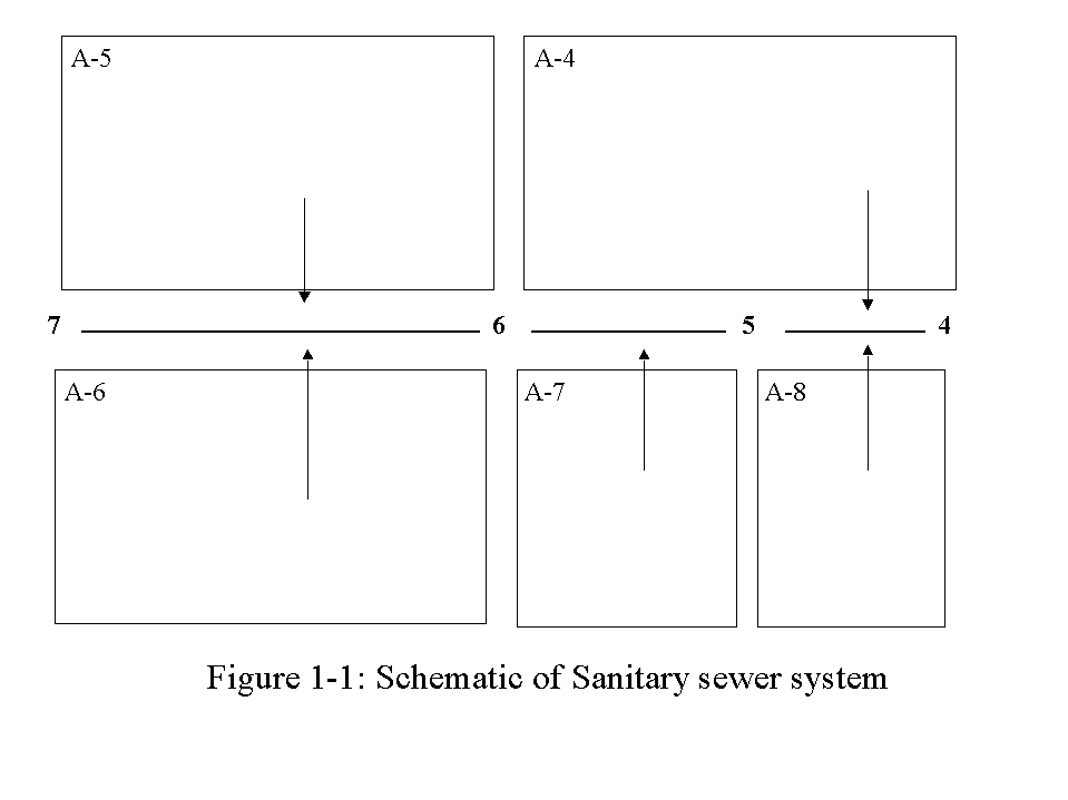
Table 1-1: Data for Problem 1
|
|
|
|
|
|
|
|
|
|
|
|
|
|
|
|
|
|
|
|
|
|
|
|
|
|
|
|
|
|
|
|
|
|
|
|
|
|
|
|
|
|
|
|
|
|
|
|
|
|
|
|
|
|
|
|
|
|
|
|
|
|
|
|
|
|
|
|
|
|
|
|
|
|
|
|
|
|
|
|
2. The inlet of a centrifugal pump is 5 ft above a water surface level. The inlet pipe has dia. 4" & length 20 ft. It contains one long-radius elbow (r/D = 8) and one swing check valve. The outlet pipe is dia. = 4" for 50 ft, then abruptly contracts to 2 (D2/D1 = 0.5, K = 3.5, see Table 11.2 for the equation) for 50 ft. It discharges 30 ft above the inlet free water surface. It contains two long radius elbows (r/D = 8) and a wide open gate valve (all in the 4 section). The pipe is cast iron (Table 10.1). Use the Manning equation, in the form hL = KQ2, to determine headloss. Take account of minor losses due to the inlet (K = 0.8), the elbows & the valves, and the contraction. Ignore the minor loss as the water leaves the outlet pipe. Use Table 11.2 for minor loss K's, as necessary.
(a) What is the added elevation?
(b) What is the added pressure?
(c) What is the added velocity head equation, in terms of flow?
(d) What is the headloss equation, in terms of flow?
(e) What is the equation relating flow to the amount of head the pump
must add to the water?
(f) What is the flowrate, given the same pump information used in class?
(g) How much power (ft lbf and hp) must be added to the water?
(h) If the pump efficiency is 80 %, What horsepower pump must be used?