ACTIVELY TUNED RESONATOR
Final Report
Problem Statement
The problem that we were presented with by the Rowan Engineering Staff was to design a surface-mounted device to actively dampen vibrations using smart rubber for Continental Tire.
Objectives
The objective of this project is to successfully use the elastomer-piezoelectric composite to dampen the vibrations of the lumped masses in the system. We also hope to gain further knowledge and understanding of the properties of the elastomer and piezoelectrics, as well as to better understand the vibration and dampening effects.
Plan
The plan
of this semester was to design, build and test. First, in order to design
our system we first had to make sure that all of the necessary materials
had been researched. As a group, we needed an understanding of the backgrounds
of both the elastomer and piezoelectrics, as well as all vibration theories
that would be used in order to design our system. After we designed the
system we then built all components and tested the system to see if our
design worked.
Background
Continental Tire is funding a project to research the effects of smart rubber to actively dampen vibrations. The smart rubber is a composite structure consisting of a silicon based elastomer and piezoelectric ceramics, the shape of which changes depending on the voltage applied, as shown in Figure 1.
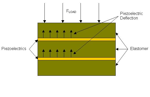
Figure 1: Elastomer-Piezoelectric Composite Structure (Side View)
Elastomer
The following elastomer was originally to be used for this project due to its ability to absorb force and spring back. This mixture is created by combining the following three chemicals:
· Polydimethylsiloxane:
[SiO(CH3)2)]n -- Elastomer Fluid
· Tetraethylorthosilicate:
[Si(OC2H5)4] -- Crosslinking Agent
· Stannous-II
Ethylexanoate -- Catalyst
However, due to a complex mixing process, along with the fact that our test sample never cured properly, we decided to create the composite with an elastomer manufactured by Gelest. This mixture, called OETM 41, contains a one to one ratio of a base and a cross-linker, with the catalyst already mixed into both components.
· Base
· Cross-linker
Piezoelectrics
As mentioned above,
we used piezoelectrics as the active component of our smart
rubber material.
In particular, we chose to use the so-called striped actuators provided
by APC International,
Ltd.
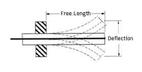
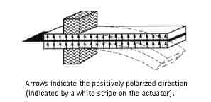
Figure 2: Striped Actuator Characteristics
This type of piezoelectric is made up of two lead zirconate titanate ceramic plates bonded to a copper center conductor. All three layers are electrical contacts. As shown in Figure 2, the upper ceramic plate is polarized with its negative side bonded to the center conductor, while the lower ceramic has its positively polarized side bonded to the center conductor. This is because the plates need to move in the same direction for a given voltage. Otherwise, they will always be pushing or pulling each other in opposite directions with the same amount of force and thus, the structure will not deform at all.
Our specific model of the striped actuator (400/200/0.6-SA) has a free length, the length that actually moves, of about 33.0 mm and is able to deflect by at least 1 mm (Figure 2) at the full driving voltage. At maximum deflection, this striped actuator is capable of exhibiting a blocking force of at least 0.4 N. The physical dimensions of the striped actuator are 1.572 x .784.
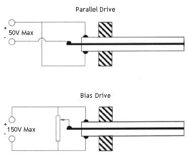
Figure 3: Drive Circuit Configurations for the Striped Actuator
There are two circuit
topologies available for the driving circuit of the striped actuator.
First, there is
the parallel drive circuit, as shown in Figure 3. In this configuration,
the striped actuator is only capable of handling a maximum driving voltage
of 50V. Since the maximum deflection can only be obtained with 150V driving
voltage, this topology can only provide 1/3 of the maximum deflection and
blocking force or about 0.3 mm at 1.3N. Another drawback to using this
configuration is that if the driving voltage ever goes above 50V, there
is a risk of depolarizing the piezoelectric such that it will no longer
deflected with voltage applied.
Second, we have the bias drive circuit, also shown in Figure 3. The striped actuator can accommodate a 150V driving voltage in this configuration and thus, the full deflection and blocking forces can be realized. In addition, there is absolutely no risk of depolarization in this case, so the piezoelectric will not accidentally cease to function. Needless to say, we chose to implement the bias drive circuit in our design.
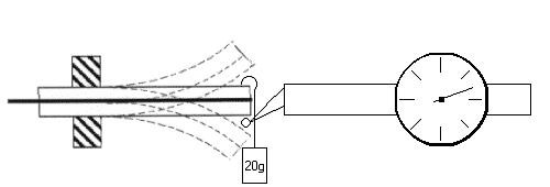
Figure 4: Striped Actuator Performance Testing Setup
We had the manufacturer specifications for the striped actuator, but we really did not know what actually happens when voltage is applied to the striped actuator. Since we would be unable to get at the piezoelectrics once they were imbedded in the elastomer, we needed to do conduct performance testing on our striped actuators before hand. Specifically, we wanted to know the deflection and blocking force of the striped actuator at a given voltage.
For our experimental
setup (Figure 4), we mounted the striped actuator in a vice, applied voltage
to deflected it completely upwards, and measured the deflection with a
dial indicator. Then, we hung known masses from the end of the striped
actuator until it returned to zero deflection. That mass then represented
the blocking force.
As a specific
example our testing, with a 40V driving voltage in the bias drive circuit
we
found that the
striped actuator deflected 0.0635 mm and exhibited a blocking force
on the order of
0.1 N. The driving voltage was about 1/3 of the maximum so the
blocking force
checks out. The deflection, however, was about five times smaller than
it should have
been for this driving voltage. Since, the overall goal of this project
really had to
do with forces and not the actual deflection seen, this discovery did not
affect our design
and we proceeded.
Mold
(a)
(b)
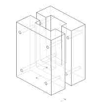
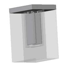
Figure 5:
(a) Mold without
Top Cap
(b) Mold with
Top Cap and Piezoelectrics
In order to build the system we first had to decide on the proper size and shape of the elastomer so that the rest of system could be built around it. Due to the fact that the piezoelectrics within the elastomer is a composite we had to consider the stiffness of both parts.
As a group, with some help from the professors, we decided that it would be best if the stiffness of the piezoelectric could be neglected. In order to do this, the general engineering assumption of a 10:1 ratio was used. Where as the height of the elastomer would be 10 times that of the total height of the piezoelectric and thus the stiffness of the piezo could be assumed to be 0. We also wanted to include a ten percent increase in area when deciding on the area surrounding the piezoelectrics for similar reasons as above. However, we feared that a ten percent increase would not be sufficient in maintaining our solid composite. So in order to assure the elastomer would not split we chose to increase the area by approximately 30%.
In order to still
neglect the stiffness of the buffer region we designed the masses to rest
only on top of
the piezoelectric area. In having the mass directly over the piezo, all
of the
forces created
would only present over the area of the electric ceramic. Once all of the
preceding considerations
were accounted for, the mold was designed.
The mold
was machined using 6061 aluminum and consists of three pieces. It has two
halves separated
by a parting line. This should allow for easy removal of the composite
once the mold had set. It also has a top cap, from which the piezoelectrics
will be suspended within the elastomer.
Masses
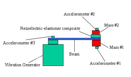
Figure 6: The Mass Spring System
The initial range for the masses was set between 0.1kg and 0.2 kg based on the problem statement. We also knew that mass #1 had to be greater than mass #2. Using the density of the elastomer we were able to find its mass, and in order to consider it a mass-less spring system the 10:1 engineering approximation was incorporated to make mass #2 ten times the mass of the elastomer. Mass #1 was then set at the upper limit, 0.2 kg, to allow for a maximum range in all other variables. Thus, mass #1 is equal to 0.440924lbs, which is 0.2 kg and mass #2 equal to 0.30436lbs, which is 10 times the mass of the elastomer. Knowing the density of aluminum to be 0.0975lb/in3, we were able to machine stock aluminum to the proper dimensions to attain the appropriate mass values.
Beam
Another part of
our system whose dimensions had to be decided and also machined was that
of the beam within the system. Our beam had to be designed with a couple
of considerations in mind. First, it was to
act as a mass-less
spring and second, the beam had to be long enough so that the
elastomer composite
could be set on top of it. Using the fact that we wanted our beam
to be as light
as possible, we decided to test two different materials, aluminum and
Plexiglas. With
every consideration in mind we decided to use Plexiglas for our final
system, because
it was thought that it would yield the best results.
In order to achieve the desired results we used vibration theories and the bases that the ratios of the stiffness of the beam to mass #1 and the stiffness of the elastomer to mass #2 must both be equal to the driving frequency of the vibration generator squared.
In order to find k1 we used the MTI Compression Testing Machine to attain values for the stiffness of the elastomer. We knew that we would be on a force range of about 10 lbs and would be seeing deflections less than 0.1 inches. In order to run the test we set the MTI Machine to run at a maximum of 10 lbs and a maximum deflection of .1 inches.
Based on our calculations we decided to use Plexiglas as the beam material due its light weight and ideal material properties. By putting the beam in bending using different masses and measuring its deflection, we were able to attain a function for its modulus of elasticity.
![]()
By using the function for E we were able to attain the proper modulus in the force range of our system. By fixing k2, m1, and m2 we were able to come up with the appropriate k1, necessary for achieving resonance. Once we attained these values we were able to compute the proper length of the beam by rearranging the equivalent stiffness formula for a beam.
![]()
We found
that by using a beam 0.39 inches thick and 0.9 inches wide the length needed
was 3.46 inches.
Driving Circuit
For full
deflection of the striped actuator piezoelectric in its bias drive, we
needed a driving circuit that would supply 150 volts across our device.
Unfortunately, the power supplies available to us did not provide a voltage
that high. To gain a better perspective on how to approach this difficult
problem, we consulted with Dr. Schmalzel who recommended that we observe
the flash circuit found in a disposable camera. For the flash to operate,
a supply of 330 volts must be applied to the xenon flash tube at the instant
the flash is to go off.
During the
reverse engineering process, we also found a website for a driving circuit
similar to the
Kodak disposable camera we were examining. Instead of a quick flash
of light that
occurred instantaneously, this circuit was designed to apply a consistent
400 volts to a
strobe light that repeated flashing at a very high frequency. Because
of the simplicity
in the circuit, as well as having the full schematic available to us, we
chose this circuit
as opposed to the Kodak circuit.
After solving
some difficulties with the type of step up transformer, we were able to
provide the striped
actuator with the 150 volts it needs for full deflection. The full schematic
is given in Figure 7, below.

Figure 7: 150V Driving Circuit for Piezoelectrics
The first momentary
contact switch (Charge Switch) allows the two transistors to create a kind
of alternating current through the transformer, since transformers only
work under AC conditions. In a sense, we are making a square wave, constantly
turning on and off the transistors. With this switching motion, the transformer
then steps up the voltage and steps down the current. The current flows
through the bridge rectifier to charge up the capacitor to 150 volts, which
is also applied to the striped actuator. Since piezoelectric devices draw
very little current, the stepping down of current caused by the transformer
does not make our system any less efficient. To bring the voltage down
from 150 volts across the piezo, we simply make the connection provided
by the second momentary contact switch (Discharge Switch), which then dumps
all of the voltage stored in the capacitor into resistor three, which goes
to ground.
Since the
voltages we are dealing with in this particular circuit can be very high,
we recommend the use of extreme caution in any attempt to actually build
this circuit.
Pulse Software
To test our
model setup, we used Pulse Software version 5.0. Pulse is a very resourceful
tool that allows us, with the aid of various other devices such as accelerometers
and vibration generators, to test our model
as we see fit.
With this software, we are able to observe the efficiency of our
piezo/elastomer
composite with frequency sweeps, a random mode to simulate how our
design will respond
to changes in frequency, and other diagnostic testing procedures,
which allow us
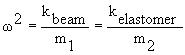
to observe various characteristics of our system. Figure X below shows
the results obtained
from Pulse 5.0. As we can see in, there is a significant drop in the
magnitude of the
first peak, seen at approximately 22.5 Hz as we begin to increase the
voltage applied
to our system. The graphs seen here plot the ratio of the first accelerometer
to the third as a function of the frequency. We can see that this magnitude
is inversely proportional to the amount of voltage applied to the system
and at a frequency of 22.5 Hz, and our goal of dampening vibrations within
a system with the masses given was achieved.
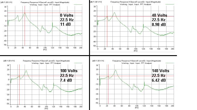
Figure 8: Composite Frequency Response (from Pulse 5.0)
Technology Impact Statements
Economic Impact
There is
a great possibility for new technology on the market. This new smart rubber
technology may bring about the need for new companies and more jobs. Hypothetically,
it could spring up its very own industry all together. If this composite
is implemented in new tires it would most likely make them into a superior
product.
However, the technology
may increase the price of manufacturing thus increasing
the price of tires.
Environmental Impact
During the production of the elastomer there are toxic fumes that are created and the proper precautions should be made, such as proper ventilation and possibly even gas masks and safety glasses for the workers that are making the mixture. Despite the fact that the elastomer is somewhat harmful when the mixture is being made, once the mold is set and the elastomer has hardened is environmentally safe. Thus as long as the manufacturer takes the proper precautions the material shouldnt have any environmental effect.
Manufacturability (of Composite)
The manufacturing of the composite consists of two parts, designing and building the molds, as well as producing the elastomer and pouring it into molds. The production of these composites may present some difficulties due to the problems faced in trying to bond the piezoelectrics with the elastomer as well as problems faced in removing the composite from the mold in tact. It was our finding that this aspect must taken with extreme caution, for if any little aspect of the composite is not perfectly set up, it could jeopardize the entire sample.
Sustainability
If the new
technology is implemented into tires it has much potential for future uses.
Even though the tires may be more costly, the elastomer composites may
save consumers money in the long run by decreasing the wear on their vehicles
as well as giving them a better ride.
Ethics
As long as
there are no patents involving the uses of this type of elastomer composite
we see no ethical problems.
Health/Safety
The health
and safety of workers producing this material should be taken into careful
consideration. Not only should all of the chemicals be properly contained
and disposed of, but also workers should be educated in the proper uses
and dangers of the chemicals involved. All workers should also be presented
with proper safety gear.
Societal Impact
If our tests
our successful there could be much possibility for development of new and
innovative technologies
in many fields other than tires. This could revolutionize the world
as we know it.
![]()
Copyright ©
2000 Team: ME-05 Junior/Senior Clinic. All Rights Reserved
Please send
comments or questions to the webmaster.