|
|
- Purpose
- To show that the current in an AC circuit is at a maximum for certain values of inductance and capacitance.
- Location
- Room 146, shelf N3 (patch cords on side of cabinet A)
- Description
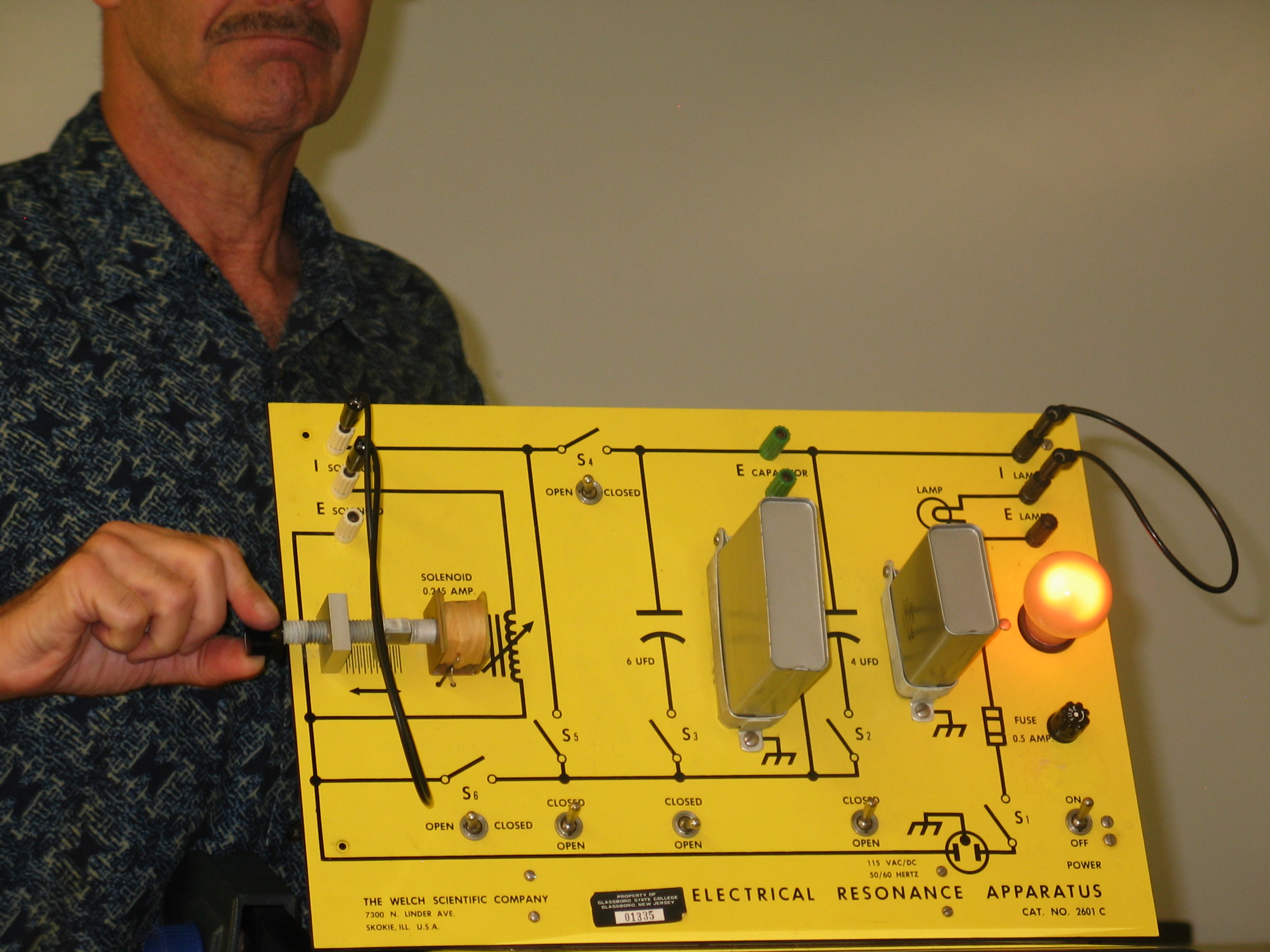
- CAUTION: THIS APPARATUS OPERATES ON 120 VAC LINE VOLTAGE.
- Make sure the power switch, S1, is in the OFF position before plugging in. Connect the two �I SOLENOID� terminals and the two �I LAMP � terminals using patch cords (if they are not already in place). Position the switches as follows: S2 � closed; S3 � open; S4 � open; S5 - closed; S6 � open. Unscrew the solenoid (i.e. variable inductance) core all the way out of the coil (see left photo). You now have a 60 Hz series LCR circuit with C= 4 microfarads. Turn the power switch, S1, on. The bulb should light dimly. (left photo)
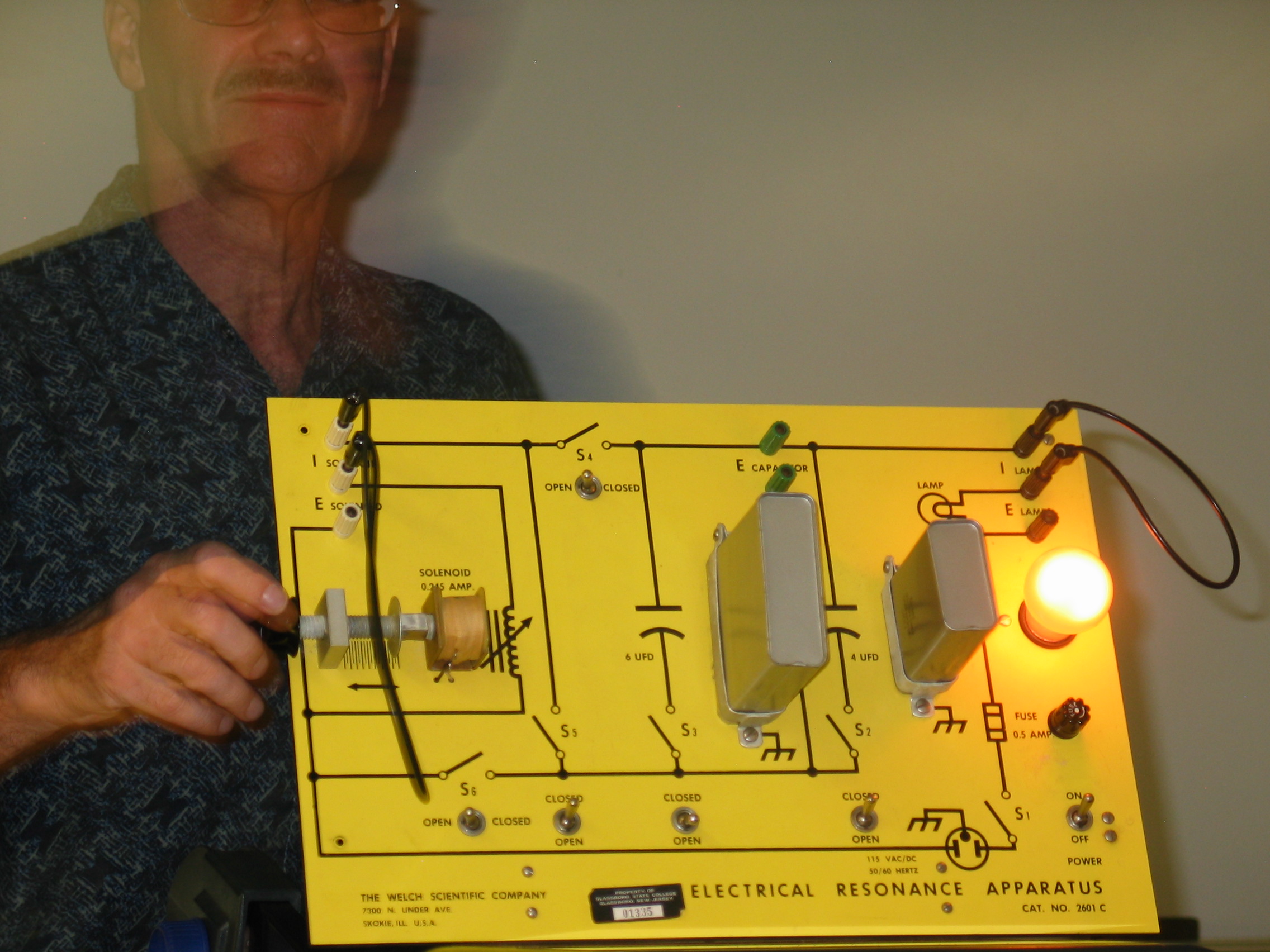
- Screw the solenoid core into the coil, thereby increasing the inductance, until the bulb glows at its brightest (right photo). Screw the solenoid further into the coil and see the bulb begin to dim, indicating less current. Go back to maximum brightness, then open S2 and close S3, showing that changing the capacitance to 6 microfarads also increases bulb brightness (i.e. more current). It should be clear that certain values of L and C result in maximum values (i.e. electrical resonances) of current.
|
