
|
Laboratory Project 4 - Digital Baseband Communications
Objectives Equipment and Software
Instrument Connectivity In this lab you will be required to send or gather data to/from various instruments at the station. To do this, you will need an active connection with the instruments by opening and refreshing the instruments in Agilent IO Libraries. Click Start>All Programs>Agilent IO Libraries Suite>Agilent Connection Expert. When the software is open, click the refresh button until the instrument icons are green. Obvioulsy the instruments will need to be powered on and past initialization before they are seen by Connection Expert. You will also need the board index (the 'number' of the interface card), and the GPIB address of the instrument. To find the board index, open the tmtool link under Matlab>Start>Toolboxes>Instrument Control>Test and Measurement Tool (tmtool) OR type >>tmtool in the Matlab command window. Expand the Hardware and then the GPIB tab on the lefthand pane. The board index should be either 7 or 8. You will see that boards that have instruments connected to them will be expandable. The GPIB addresses are consistent across all instruments in the Mixed Signals Laboratory:
-> Please read the full connectivity guide for further details
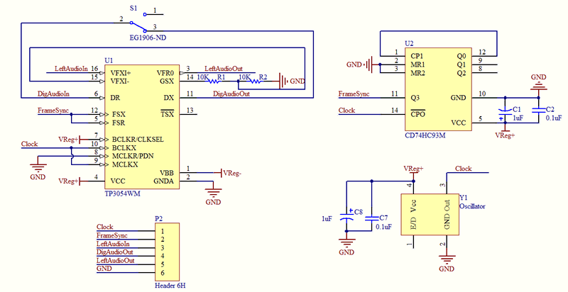
Project Requirements * The circuit you are required to use is shown in Figure 1 below. The SG-531P Crystal Oscillator generates a a pulse train at 1.544 MHz that is used both as a Transmit/Receive Master Clock and a Bit Clock for shifting digital data out of and into the TP3054 CODEC. The CD74HCT93 4-Bit Binary Ripple Counter is used to divide the Master Clock frequency by a factor of 16; this is used to generate the frame synchronization pulses for the CODEC. Print out and study the data sheets for all of the chips before starting on this lab project. * As soon as you power on the circuit, check if the transmit master clock (MCLKX), bit clock (BCLKX) and frame sync (FSX) inputs are being fed accurately. * Feed a 1 kHz sine wave into the non-inverting input of the transmit input amplifier (VFXI+). Observe the bitstream at the PCM data output pin (Dx). Vary the input signal amplitude and verify that the output bitstream also varies. * Test whether your CODEC system is working by feeding the output bitstream into the receive data input pin (DR). The input analog signal must be resynthesized at the analog output pin (VFRO). What is the quantization error? * Repeat the experiment using multi-tone audio-frequency signals obtained from the PC's sound card. * Design and conduct an experiment to determine the input-output transfer characteristics of the CODEC. You are required to generate a table that contains the input analog voltage and the corresponding output bitstream. Bonus Exercise : Design and conduct an experiment that introduces random bit-flips in the digital input bitstream of the CODEC - characterize its performance as the bit error rate is varied. * Your lab project report should be in the usual format.
Click here for required lab project report format. Click here for suggestions for a good lab report. References:
|
